
CHAPTER - 01
(THERMOSET INJECTION MOULDING)
We Use Plastics........From Morning to Evening........🤔🤔
THERMOSET INJECTION MOULDING
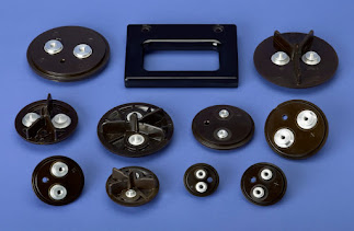
Electrical switches, handles of various utensils etc. by thermoset injecting molding using thermoset materials in to a closed mould which is relatively cooled.

PROPERTIES OF THERMOSET MATERIALS
- Undergoes a curing process during heating at mould and desired shape of the component causing the permanent change cross thinking in the molecular structure.
- Once cured they cannot be remitted.
- Thermoset polymer have their chance crossing by the covalent bond thermoset plastic under a physical as well as chemical change during processing of which is irreversible.
EXAMPLES OF THERMOSET MATERIALS
- Phenol Formaldehyde (PF)
- Melamine Formaldehyde (MF)
- Urea Formaldehyde (UF)
- Epoxy Resin
- Sheet Molding Compound (SMC)- High-strength composite material consisting mainly a thermosetting resin, fillers, and fiber reinforcement.
- Bulk Molding Compound (BMC)- Bulky mixture of chopped glass fibers, resin paste and fillers Dough Molding Compound
- (DMC)- It is a ready-to-mold, glass-fiber reinforced thermoset polymer Polyester and PU
THERMOSET INJECTION MOULDING (TIM)
In this process cold material is injected into an extremely hot mold to create a part. This process cures the part so it can never be melted again.

PROCESS OF TIM
 |
TIM PROCESSING GUIDE

TECHNICAL INFORMATION

THERMOSET MOLDING SEQUENCE
Breathing Sequence:
- Mould Close→ Mould Lock → Injection → Pre-Moulding Delay → Mould Opens up to breathing set stroke→ Breathing Delay→ Mould Lock → Hold On→ Curing Time→ Mould Open → Ejector Forward→ Ejector Return.
- Breathing Sequence helps to remove gases entrapment inside the mould which leads voids & Burn marks on Thermoset Moulding parts.
PRECAUTIONS OF BARREL SAFETY-TIM
- Do not have a prolonged stoppage of machine with thermoset material inside the barrel.
- Remove nozzle when ever there is power cut OFF.
- Remove Nozzle, empty barrel material, purge once with PP material and keep screw fully forward position before shut down of the machine.
- Clean Nozzle Thread area, Barrel Thread area and Apply high temperature grease on nozzle thread (to prevent seizure of the nozzle) during fitment of nozzle into the barrel.
- Use proper ring spanner and brass hammer for removing and fixing nozzle into the barrel.
- Do not inject when there is a nozzle blockage.
- Use either brass or copper rod to clean the Nozzle & Mould.
- Clean the nozzle at the end of every shift (This need to be practised even when the machine runs without any problem).
NOZZLE BLOCKAGE
Nozzle blockage is one of the frequently facing problem in moulding thermoset plastic Raw Material Following actions would helps to reduce nozzle blockage-
- Nozzle radius should be lesser than the mould sprue radius by minimum 1 mm
- Nozzle orifice should be lesser than the mould sprue orifice by minimum 1 mm.
- Use twin cylinder injection unit for better alignment & uniform contact force distributions
- Nozzle centring should be less than 0.1 mm.
- Use Injection Unit retraction option moulding thermoset material
**By monitoring mould heater current continually helps better process consistency & reduce rejections.
TYPES OF TIM
- Plunger type TIM
- Reciprocating Screw Type TIM

BENEFITS OF TIM
Thermoset injection moulding has several specific applications which depend on the original polymer or compound. In general, thermoset plastics provide thermal and electrical insulation – which is useful for electronic applications.
- Heat Resistant- Thermoset plastics can withstand elevated temperatures because they will not remelt – some as high as 370°C , and some as low as way below 0°C.
- Excellent Load-bearing Capacity- Lightweight thermoset polymers often have a surprising load-bearing capacity, both in compression and shear, especially when flexible.
- Shock Absorbent-Thermoset plastics tend to have significant impact resistance and can be shock-absorbing. The final properties of the compound can range in hardness and flexibility.
- Resistant to Harsh Chemicals- They are also often resistant to chemicals and solvents, proving reliable for use in applications that include liquids, like the medical industry, because they don’t swell or deteriorate.
- Good properties for medical applications- Some thermoset compounds, specifically silicone, are approved for medical applications because they have low toxicity and do not react with the skin or internal organs or fluids.p
FAULTS & REMEDIES
- Porosity
- Blisters
- Cracks
- Clouds
- Colour
- Streaks
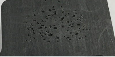
POROSITY
Uncompressed areas appearing mostly at the end of a flow path or around weld lines, also at domes, ribs, and thin-wall areas. The surface is rough, there are gloss differences, and melting is incomplete, possibly with colour changes.
Causes-
- Mostly insufficient compacting of the moulding compound.
- Low shot volume,
- Insufficient pressure transfer,
- Insufficient venting to allow volumetric filling
Troubleshooting-
- Increase back pressure.
- Check steadiness of plasticising time
- Check mould temperatures
- Run process with melt cushion
BLISTERS
Blisters are gas inclusions that can cause deformations on the surface of the moulded part. They can appear as large areas spread over the entire moulded part (under-curing), or as small blisters (over-curing, pimples, fish eyes).

Causes-
- When the peripheral layer cures too fast compared to rest of the part, volatile in the compound cannot escape during curing,
- When gas pressure forces volatile in the compound to the outer layer, lack of counter pressure it occurs.
Troubleshooting-
- Reduce mould wall temperature.
- Reduce curing time
- Reduce injection rate.
- Increase holding pressure & time.
CRACKS
Small gaps that often appear near gates, wall thickness variations, weld lines, restricted flow areas, blisters, inserts, or sharp edges.

- An-isotropic shrinkage,
- Varying temperatures,
- Shrinkage due to gas incursions.
- De-moulding forces,
- Adjust holding pressure.
- Adjust injection rate
- Increase back-pressure
- Optimize mould wall temperature.
CLOUDS
An area of the part with boundaries transverse to the direction of flow that appears matte compared to the rest of the surface. This defect often occurs around gates and after wall thickness variations. Often these clouds can be wiped off.

Causes-
- Lubricant content in the moulding compound is too high.
- Short pressure releases
- Avoid pressure relief during changeover from injection to holding pressure.
- Reduce injection speed..
- Reduce mould wall temperature.
- Reduce lubricant in moulding compound.
COLOUR STREAKS
Streaks visible on the part surface as discolorations.They are oriented either as oblong stripes or transverse to the flow direction.

Causes-
- Uneven distribution of the material components.
- Different orientation of the colour pigments on the surface of the part.
- Thermal damage of the moulding compound can also cause colour changes.
- Check moulding compound for contamination.
- Use cleaning material to clean the hopper.
- Reduce dust content in surrounding air
CHAPTER - 02
(ADVANCE INJECTION MOULDING)
Advanced Injection Molding Technologies covers the most recent and important developments in advanced injection molding technologies, such as intelligent process control; technology innovations and computer simulation for emerging special injection molding processes-
- Microinjection molding
- Microcellular injection molding
- Structural foam molding
- Water-assisted injection molding
- Thin wall product moulding
- Multi material and Multi-Colour moulding
- All Electric Injection Moulding
STRUCTURAL FOAM MOLDING
What is Structural Foam ?
A cellular plastic is one in which the outer surface is denser than the inner layers. The core of the moulding is of a honeycomb nature and less dense than the outer surface. The combination results in a moulding of a high stiffness ratio compared with non-structural foam moulding.


Overview: Structural Foam Molding-
Structural foam molding is a low pressure injection molding process where an nitrogen, carbon dioxide gas is introduced into melted polymer for the purpose of reducing density and weight of the finished product while increasing the strength. Various types of plastic materials used in structural foam molding.
.jpg)
Plastic Materials-
- Thermoplastic (ABS, PS, PE, PVC, Polysulfone, Acrylics)
- Thermoset (Mostly Urethane)
- Latex
- Physical Blowing Agents (PBA)- Pressurized gasses- N2, CO2
- Chemical Blowing Agents (CBA)- Class of polymer additives
PROCESS
- Melted plastic has filled in injection unit and is ready to inject ito the accumulator.
- The melted plastic is transformed into the accumulator section ready for the gases to be injected.
- Both Ball valve present any escape at this stage gases injection into the melted plastic under pressure the top Ball valve present a feedback into the injection unit the front wall present a beeping of the metal throughout the nozzle.
- Injection speed depends upon gate and runners design.
- Front valve now actuate and allow to injection of the molten plastic.
- Due to lower atmospheric pressure expand the melted plastic to fill the mold.
- Material cooled,solid and product ejected.
- The outer surface skins and core is foamed.

PROCESS PARAMETERS
Plastic Materials | Injection Pressure (kg/cm2) | Processing Temperature (oC) |
HDPE | 7-35 | 200-300 |
PP | 7-35 | 200-275 |
PC | 7-35 | 280-310 |
ABS | 7-35 | 180-240 |
TYPES OF FOAM MOLDING
- Low Pressure Foam Molding-
- Less pressure 200-600 psi.
- Inject a short shot
- Pressure generated by pressurized gasses

- High Pressure Foam Molding-
- CBA Used
- Inject a full shot
- CBA expand polymer melt
- Control density by adjusting mold height
.jpg)
ADVANTAGE OF FOAM MOLDING
- Part weight reduced 10% to 30%.
- Increased strength and stiffness due to honeycomb structure.
- Capable of molding large, complex parts without sink marks.
- Highest strength-to-weight ratio compared to alternative manufacturing methods and materials.
- Can replace concrete, sheet metal, metal castings, wood, fiberglass, rotational molding and blow molding in a variety of applications
- Superior impact resistance.
- More rigid than a solid part.
- Low part stress and warpage.
- Consistent surface finish.
FAULTS AND REMEDIES
FAULTS | CAUSES | REMEDIES |
Incomplete filling of mold |
|
|
Internal voids |
|
|
Pin or holes in surface |
|
|
Part density varies |
|
|
APPLICATIONS
- Business Machine Housings
- Point of Sale Display Components
- Medical Instruments housing
- Automobile parts
- Shipping crates
- Furniture
GAS ASSIST INJECTION MOLDING
- The basic concept of the gas-assisted molding process is quite similar to the regular injection molding process.
- In gas-assisted molding, the plastic material is injected into the mold cavities like the regular injection molding process but only up to 70%~80% of the mold volume.
- The melted plastic in contact with the mold walls begins to solidify, then nitrogen gas is injected into the mold through strategically designed and placed gas inlets, providing pressure that pushes the plastic into the mold extremities.
- The path of the bubble is controlled by taking the path of least resistance through the hottest, least viscous plastic, which keeps it centered from the colder walls of the mold.
- Finally the molded part is ejected like the regular injection molding process.

MATERIALS USED
- PMMA
- PS
- TPE
- POM
- PPO
- PP
- PC
- PA
- ABS
- PC
PROCESS PARAMETERS
- Materials properties
- Gas pressure
- Melt temperature
- Delay time
- Gas injection time
- Pre filled polymer volume fraction
- Cycle time
- Clamping force
ADVANTAGES
- Strength - Increased strength and rigidity through the creation of tubular structures in the part geometry.
- Weight Reduction - Thick sections can be cored out with gas to reduce weight.
- Design Flexibility - Ability to add thick sections as required and core them using gas assist technology.
- Surface Finish - Better surface finish than structural foam more like standard injection molding.
FAULTS AND REMEDIES
Faults | Cause | Remedies |
Burst after demoulding |
|
|
Sink marks: |
|
|
Unstable weight |
|
|
Finger effect: |
|
|
APPLICATIONS OF GAS IM
- Arms rest and chairs handles
- Panels and frames
- TV cabinet
- Suitcase shells
- Sports equipments
- Cover for Washing machine
- Computer housing
THIN WALL PRODUCT MOLDING
- Thin wall injection molding is a specialized form of conventional injection molding
- It focuses on mass-producing plastic parts that are thin and light so that material cost savings
- This molding can be made and cycle times can be as short as possible.
- Shorter cycle times means higher productivity and lower costs per part.
- The size of a part puts a limit on how thin the wall thickness can be. For producing products nominal wall thickness less than 1.2mm. or below length to wall thickness ratio ranging from 100:1 or more (L/T Ratio).
- The reduction of component thickness depends upon several parameters-
- Melt Flow Behaviour
- Maximum Injection Pressure
- Component Strength
- Standards and legal Regulations

MATERIALS USED
- High-density polyethylene (HDPE)
- Low-density polyethylene (LDPE)
- Polypropylene (PP)
- Nylon (PA)
ADVANTAGE
- Low-cost
- Safe and sanitary plastic components.
- Saves materials
- Light weight
- Reduce cooling time
- Lower cycle time which increase production
- Selecting suitable materials
- Material knowledge
- Strictly using rheological simulation program (ANSYS Polyflow)
- Suitable part design
- Suitable tool design.
- Suitable for less than 1.5 mm. wall thickness and flow ratio less than 100.
- Flow path for thin molding should be 1/10th of conventional molding.
- Fill time is less than 0.5sec
- High injection and clamping pressure
- High performance controls and hydraulics
- Injection unit is equipped with accumulator
- High clamping tonnage around double than conventional molding
- Air vent in the mold is essential
- The barrel size should be less to avoid the excessive residence time.
- The cycle time is under 10 sec. and screw speed is 100 cm/sec. So precise machine control is required.
- The mold rigidity, cooling system and proper gate selection and location are also important.
- The injection pressure of 2800 kg/cm2 is used to make PC battery housing (less than 0.5 mm) where as the computer housing of 1.5 mm thick needs injection pressure of 2040 kg/cm2.
APPLICATIONS
- Plastic housings & bakery packaging
- Electronic housing & agriculture
- Automotive & food industry
- Plastic containers & consumer electronics
- Cell phone & food packaging
- Frozen food packaging
- Meat & soup packaging
MULTI MATERIAL AND MULTI COLOUR MOLDING
Multi-material injection moulding (overinjection) is one of the most widespread technologies for manufacturing plastic components. The process is based on the injection of two or more materials in a single mould and process.It includes two-shot injection molding, like co-injection, double injection molding and sandwich injection molding, etc. The basic idea of multi-material injection molding is to combine 2 or more materials with different properties to increase product value.
The three most widely used methods of MM & MCM molding-
- Multi-component
- Multi-shot Over-molding
MULTI COMPONENT MOLDING
It is known as co-injection molding, multi-component injection molding describes insertion of multiple viscous materials injected simultaneously, as opposed to placing one material as an additional layer relative to another. It creates a sandwich-like structure where both materials mold around each other as dissimilar liquids, and exist in such a state at the same time. Relative to the part center, materials can be injected concentrically using the same mold/gate, or regionally using gates at different locations.

MULTI SHOT AND OVER MOLDING
It is known as sequential injection molding. It is a plastic molding process in which two different plastic resins are molded together in a single machining cycle. Heated materials are inserted into the mold in a very specific sequence one after another. This creates a layering effect between materials while maintaining relatively high-energy interactions at material boundaries. This is important because it implies that the inter-layer bonds are stronger in many cases than when the layers are applied to a previously cooled part, as is more closely the case of over molding.

TWO-SHOT MOLDING- ACTIVE GRILL SHUTTER

ADVANTAGE
- Increased production
- Less shrinkage and better gas barrier performance
- Enhances the product’s value
- Innovation and improvement of the aesthetic design and product
- Increase in mechanical features
- Reduction of part assembly, which allows for a cheaper product
- High personalisation of the final results
APPLICATIONS
- Thin wall containers and tubs, clear or colored
- PET performs Caps and closures
- Dairy containers
- Single-use coffee pods/capsules
- Retortable clear plastic cans (Milacron Klear Can)
- Medical applications – bottles, vials, etc.
- Shelf Differentiation: aesthetic packaging, color gradation
- Movable segments or components
- Rigid substrates with soft grips

ALL ELECTRIC INJECTION MOLDING
- To make injection moulding machine without hydraulic development in servo Motors during late 70's opened up as opportunity for very energy efficient are electric injection moulding machine. All electrical modelling machine without hydraulics developed by JSW, Fanuc, butterfield and many others.
- Since demand for power during moulding cycle is not constant but it is variable. Therefore the power is the wastage during low demand period in addition there is efficiency factor of 82 90% between electric motor and hydraulic pump.
- All electric machine is hydraulic activator is replaced by a powertrain consisting of AC Servo Motor of suitable power rating with its control for speed, ball screw and two pulleys with one belt.
- Feedback is provided by high resolution position feedback device like optical encoder. it means toggle is operated by servomotor, screw is rotated by a separate servomotor, ejector is operated by a servomotor, and injection and suck back by a separate servomotor, and injection unit movement by a different servo motor.


ADVANTAGE
- 25 to 60% lower power consumption than hydraulic machine
- Cleanliness around the machine is ensure in absence of oil
- Silent working environment
- No Fire protection maintenance is needed
- Fully loop control with a less fluctuation in position and velocity
- In absence of oil water requirement is reduced by over 70%
- Machine length also reduced by approx 15 %
CHAPTER - 03
(FIBER REINFORCED PLASTIC )
- Reinforced plastics-Generally similar to laminates in a number of applications.
- FRP- Polymeric resin and reinforcement usually in fibre form along with other additives such as filler, catalyst, initiator, lubricants etc.
- Both thermoplastics and thermosets are used in FRP but thermosets are most widely used.
- A reinforced plastic consists of two main components: a matrix, which may be either thermosetting or thermoplastics and reinforcing filler, which usually takes the form of fibres.
- Other materials such as fillers, pigments, catalyst may also be present.
- In general the matrix has a low strength in comparison to the reinforcement, which is also much stiffer, but brittle.
- Composite material made of a polymer matrix reinforced with fibres. The fibres are usually glass (in fibreglass), carbon (in carbon-fibre-reinforced polymer), aramid fiber. Some fibres such as paper, wood have been used.
- In FRP polymer is usually an epoxy, vinyl ester, or polyester thermosetting plastic, though phenol formaldehyde resins are still in use.
- FRPs are commonly used in the aerospace, automotive, marine, and construction industries. They are commonly found in ballistic armour apparatuses.
- FRP- Polymeric resin and reinforcement usually in fibre form along with other additives such as filler, catalyst, initiator, lubricants etc.


Why FRP Used -
Reinforced plastics comprise a large portion of the industry, because
- High strength/weight ratio.
- Rigidity
- Virtually unlimited moulding size.
- Ease of fabrication.
- Wide range of manufacturing techniques.
- Low capital out lay.
- Design versatility.
- Excellent water resistance.
- Chemical resistance.
- Weathering resistance.